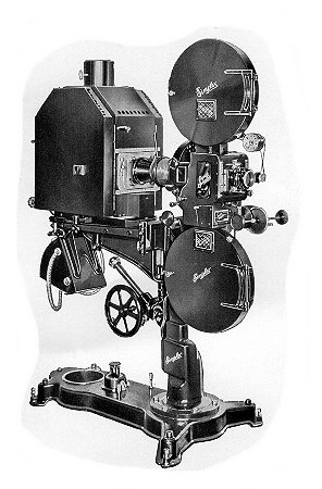
THE NEW SUPER SIMPLEX
With Type R Pedestal and H.C. High Intensity Lamp,
Designed for All Types of Sound Equipment.
The New Super Simplex
Foreword
THE NEW SUPER SIMPLEX
With Type R Pedestal and H.C. High Intensity Lamp,
Designed for All Types of Sound Equipment.
Foreword
The installation and operating instructions for the new Super Simplex must not in any way be considered as a textbook for general and widespread use. We take for granted that these instructions will go only to experienced projectionists who will need a certain amount of practical information for their guidance in connection with the Super Simplex, but are thoroughly competent to handle all ordinary problems for themselves.
We have endeavored to be as brief as possible and to cover only points which absolutely demand explanations and instructions. It is, therefore, not unlikely that there are some omissions. These we feel convinced will for the most part cover minor points, but it is possible that we may have omitted some information which generally or in special cases may be urgently needed. We would, therefore, greatly appreciate requests for further information when desired and we also welcome suggestions and criticisms.
The new Super Simplex is a great advance over any other projector manufactured by this or any other manufacturer of motion picture machines. While we do not claim that it is the final word in motion picture projectors, it is unquestionably the very latest and positively justifies the name Super Simplex. There is a natural tendency to give reasons for our confidence in the superiority of the Super Simplex but such explanations do not properly belong in a book of instructions. We do, however, sincerely believe that if the directions we give are carefully followed out the Super Simplex will be an invaluable aid to the expert and experienced projectionist.
OPERATING INSTRUCTIONS
Oiling System:
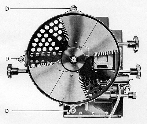
The simplest and yet most efficient oiling system now forms part of the Super Simplex main frame assembly. All bearings in the frame are now reached by means of oil tubes conveniently located on the gear case side of the mechanism, see A, Fig. 1. There is but one bearing which has a direct oil hole on this side of the apparatus; this oil hole is for the lubrication of the rear bearing of the shutter shaft and is shown at C, Fig. 1. Do not overlook this oil hole when oiling the mechanism.
All oil tubes but one are plainly visible upon opening the mechanism door on the gear enclosure side and no further instruction with regard to them is necessary, except to state that all oil tubes which are immediately visible should receive oil at least once a day. The visible oil tubes have within them a wick which reaches the bearing and a few drops placed within the tubes each day will be more than sufficient to take care of proper lubrication. Be careful to note that one of these tubes comes out through the top of the mechanism.
Oiling Intermittent Movement Casing:
The one oil tube which is not immediately visible is that which carries oil directly into the intermittent case and there is no wick in this particular tube. The procedure for placing oil in the intermittent casing is as follows:
There are other minor oil holes which should receive oil occasionally, two which provide lubrication to the bearings of the "Film Gate" opening shaft, one which provides lubrication to the rear bearing of the "Frame" shaft and two which provide lubrication to the bearing of the "Shutter Adjusting Shaft." The latter oil holes will be found beneath the framing lamp assembly. The only other oil hole on the mechanism is the one supplying oil to the outer bearing of the intermittent sprocket and this bearing is oiled through the ball oilcap, D, Fig. 2, in exactly the same manner as in the old type Simplex mechanism with double bearing movement. Of course, a small drop of oil should occasionally be placed on all slipping and sliding parts in order that they may work freely at all times and also on the gear teeth so that the mechanism may operate smoothly.
Sound Aperture and Picture Centering Device:
The Super Simplex Projector is supplied with the vertical sliding aperture plate in which are two standard apertures, one having the standard dimensions for straight silent film projection (.906 x .6795) and the other having standard dimensions for sound film projection (.800 x .6795), or the proportional aperture (.800 x .607) for the projection of sound film to give a screen picture of the same dimensions as obtained with the standard silent projection aperture. With the use of this latter aperture it is necessary to change to shorter focal length lenses and this can be readily and quickly done in the Super Simplex as is explained under MOUNTING LENSES. It is also possible to furnish Super Simplex Projectors with the lateral type of sliding aperture in which all types of apertures may be used interchangeably if desired.
Aperture Plate:
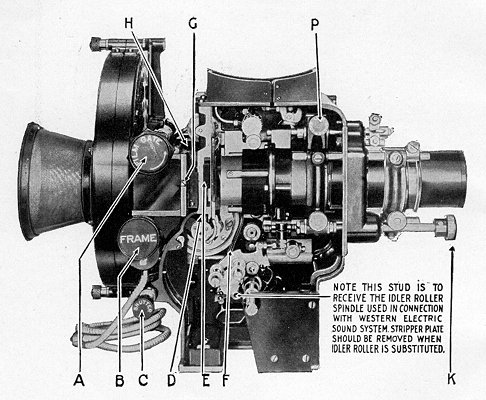
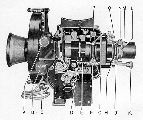
The aperture plate, E, Fig. 2, slides vertically behind the film tracks on the film trap. In its upper position it carries the standard silent film aperture. When slipped into the lower position it carries the standard sound film aperture or the standard proportional aperture, depending on which was ordered with the projector. When using the standard sound film aperture or the proportional aperture it is obvious that the lens mount with relation to the center of the aperture is off center, due to the masking of the sound track and, therefore, throws the picture to one side on the screen. We have designed and built into the Super Simplex Projector the ideal method of correcting this condition. On the front and top of the lens mount, outside of the mechanism, see Fig. 3, will be
found a lever, A, which may be thrown laterally from left to right. In the position shown the lens is accurately centered on the standard or proportional sound film aperture, and thrown over to the left position it will be centered for the standard silent or disc aperture. Stops B, Fig. 3, are provided on this adjustment so that the length of its throw may be pre-determined in order that the lens may also come into the correct relation with the projection apertures and the projected picture; these stops fetch up against the stationary stop shaft C. Ideal results are secured with this arrangement when using the proportional aperture because when this aperture is used and a change made to the correct shorter focal length lens, a picture of the same proportions as that projected through the silent film aperture is projected to the screen, and by simply moving the lens centering lever to its correct position no further change is necessary on the stage, such as sliding in tabs or masks. Just within the glass door of the mechanism in the upper right-hand corner, see P, Figs. 2 and 5, will be found a lens holder lock screw. This screw is attached to a clamp provided in order that the lens centering level may, if desired, be locked in fixed position and also to apply a slight tension that eliminates vibration of the lens centering unit.
New Super Simplex Revolving Shutter:
Great improvements in shutter design have been incorporated in this shutter. Its extremely large diameter provides for a greatly increased screen illumination and, because of its position with relation to the lamphouse and aperture, it greatly reduces the heat at the aperture, oper-
ating as it does between the light source and the film. In addition to this, the shutter is so designed that it directs a strong blast of cool air over the entire front of the mechanism and particularly into the aperture, so that the cooling effect obtained during its operation reduces the heat at the aperture approximately seventy-five per cent over the older types of equipment. It will be appreciated that this is of utmost importance when projecting sound film because it reaches the sound projection aperture in an undistorted condition. In addition to this tremendous advantage, the shutter blades are vignetted so that a pronounced dissolving effect is obtained while the intermittent movement is in operation and when the cut-off blade passes through the light beam.
The shutter construction is shown in Fig. 4. Very little instruction is needed with regard to the new shutter inasmuch as the method to be followed in setting it is exactly the same as that on the old type Simplex, viz. bring the intermittent sprocket from rest down two teeth, using the lower end of the film shoes as a guide; then set the center of the shutter on the optical axis, locking it in this position. Care should be taken, of course, to see that the throw of the shutter adjusting screw C, Fig. 2 is set centrally in order that the shutter may be adjusted in both directions if it is not set at exactly the proper position on the shaft. The entire shutter may be exposed by removing the front shutter guard. This is accomplished by simply removing the three nuts and washers D, Fig. 4, and slipping the front shutter guard from its supporting studs.
Eye Shield:
The eye shield on the Super Simplex has been so designed to protect the projectionists eyes entirely from the bright rays from the spot at the aperture. This eye shield is an entirely enclosed device and the colored glass therein may be readily removed for cleaning by loosening screw G, Fig. 2. This eye shield together with the framing and threading lamp are attached by means of screws to the front section of the shutter guard. A slot is provided in the eye shield assembly just behind the aperture, see H, Fig. 2, so that change-over devices using an aperture cut-off may be readily adapted.
Threading and Framing Lamp:
An excellent threading and framing lamp has been provided and is mounted below the eye shield assembly, see D, Fig. 3. This lamp directs a strong beam of light up behind the eye shield to the aperture and by this means it is possible for the projectionist to place the film in frame readily while threading the projector. A small switch is provided, F, Fig. 3, by means of which the lamp may be thrown on or off at will, and four feet of armored cable is supplied for connecting the framing lamp assembly to any convenient source of 110 volt supply.
The lamp used in the framing lamp assembly is of special design and is of 10 watt capacity operating at 110 volts. Should it become necessary to replace this lamp, loosen screws which hold switch assembly and lamp socket in lacquered barrel; the entire assembly may then be removed and lamp readily replaced.
Gate Opening, Framing and Shutter Adjusting Knobs:
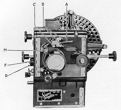
These knobs are plainly visible on the projector and very little need be said with regard to their operation. The film gate knob, A, Figs. 2 and 5, controls both the film gate latch and the gate opening device, and it is turned about a quarter turn to the left as indicated by the arrow thereon to open the gate. When the gate is opened, upon being released by lever F, Fig. 2, it both closes and latches readily. When the gate is closed it should be closed gently and a slight pressure of the finger given it in order to make sure that it latches properly. The framing handle B, Figs. 2 and 5, is so mounted upon the shaft that when the word "Frame" is read in a horizontal position, as indicated in Figs. 2 and 5, the framing device is centrally located, allowing approximately the same throw to right and left for framing purposes.
The shutter adjusting knob, C, Figs. 2 and 5, is connected through the gear train and shafts to the shutter shaft and turning it in either direction will revolve the shutter shaft to the right or left respectively, so that the shutter may be accurately set with the projector in operation after it has been temporarily set and locked on the shutter side. Care should be taken to see that an equal amount of throw is allowed in the shutter adjusting mechanism when the shutter is locked upon the shaft.
The lens focusing knob, K, Figs. 2 and 5, projects out through the front of the mechanism and is of the micrometer type. One complete turn of this knob moves the lens mount forward or backward approximately .040", depending upon the direction of its rotation.
Lens Mount:
The lens mount is so constructed that it will rigidly support any type of lens having dimensions now established by the Standards Committee of the Society of Motion Picture Engineers; these call for an outside barrel diameter on the series 2 lens of 2-25/32". We will confine our attention for the moment strictly to lenses of the series 2 or No. 2 type, and lenses of the series 1 or quarter size type will be treated later in a special paragraph.
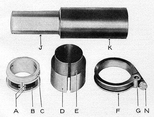
The lenses are held firmly in place by means of two lens clamps, one within the projector mechanism, G, Fig. 5, and one on the outside on front of the mechanism, see H, Fig. 5. The lens mount is made to standard dimensions, as above mentioned, and will take any standard Bausch & Lomb series 2, Gundlach half size, Snaplite half size and Solex lens. It will also accommodate other lenses of American manufacture having standard dimensions. Half size Ross lenses may also be accommodated but it will be found that in many focal lengths the large barrel diameter, see K, Fig. 6, is several thousandths of an inch below the American standard, and where this discrepancy is discovered it will be necessary sometimes to use shims similar to that shown at D, Fig. 6, in the front clamp H, Fig. 5. Two of these shims are supplied with each Super Simplex mechanism, one having a thickness of .005" and the other .010". However, one or both of these shims will bring the off standard dimension of these lenses up to standard. It may be interesting to note that the manufacturers of Ross lenses are now making all their outside barrel dimensions the equivalent of the American standard.
With series 2 or half size lenses of various focal lengths it will be necessary to use especially designed
adapters on the rear element so that the lens may be properly accommodated
in the rear lens clamp, G, Fig. 5, and complete data
with regard to these adapters will be found in succeeding pages.
Mounting Lenses:
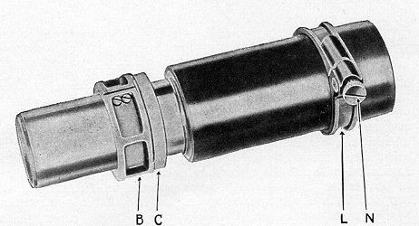
When setting lenses in the Super Simplex lens mount the following procedure must be observed: By turning the lens focusing knob, K, Fig. 5, set the focusing nut E, Fig. 5, centrally on the focusing thread D, Fig. 5. Loosen the lens clamp screws F and J, Fig. 5. Slip the rear lens adapter B, Fig. 6 (if one is necessary) over the rear combination lens without clamping it on the barrel, as shown in Fig. 7. Slip the lens in through the front of the lens mount and bring it into approximate focus by sliding it back and forth in the mount. When in focus, slightly tighten the front lens clamp screw, J, Fig. 5, so that the lens will not slip. Slip the rear lens adapter B, Fig. 7, along the lens until it centers in the rear lens clamp G, Fig. 5. Loosen the front lens clamp screw J, Fig. 5, and carefully remove the lens. Tighten the clamp screws A, Fig. 6, so that adapter will then be tightly clamped on the rear lens combination. The lens is then permanently assembled for future use and may be accurately focused by the focusing knob in the regular way. As before mentioned, with some Ross lenses it may be necessary to shim them up in order to bring them up to the standard diameter to clamp them in the front lens clamp H, Fig. 5, and the shims provided should be used for this purpose.
With all Ross lenses there is provided by the manufacturers a shim shown at E, Fig. 6. This shim must
always be used in connection with the adapter B, Fig. 6. The length of this shim should be reduced so that it does not project beyond the adapter B, Figs. 6 and 7, or interference will be experienced between the shim and the lens mount. This applies to both large and small diameter Ross lenses.
Series 1 and Quarter Size Lenses:
Series 1 and quarter size lenses of all makes may be readily accommodated in the Super Simplex lens mount by the use of adapters especially made for them. With lenses of this type it is necessary to use an adapter similar to that shown at B, Fig. 6. After selecting the correct adapter, slip it over the series 1 or quarter size lens with the threaded portion towards the screen. Select a half size lens tube as explained in succeeding data and screw it tightly on the half size adapter. Your series 1 or quarter size lens will now have the appearance of a half size lens. Do not at this time clamp the adapter tightly on the lens. Slip the lens, as above assembly, into the mount as set forth for half size lenses, seating the half size adapter B, Fig. 6, under the rear lens clamp G, Fig. 5, and gently lock clamp screws F and J, Fig. 5. The series 1 or quarter size lens may be pushed back and forth in its adapter B, Fig. 6, until it comes into approximate focus. The entire lens should now be removed and the two clamp screws A, Fig. 6, in the adapter tightened solidly on the lens. Insert the lens in the mount in the regular way, tighten screws F and J and focus accurately by turning lens focusing knob K, Fig. 5. Due to the many different designs of lenses it is necessary to select the correct adapters for use in connection with them. All of the necessary data with regard to this matter is supplied in succeeding pages, commencing with page 13, and while it may appear complicated at first glance, it will be readily appreciated that lenses must be properly assembled for use in the Super Simplex mount. Once done, the tremendous advantages accruing to the user of the Super Simplex through the excellent design of the lens mount will be fully realized after the projector is placed in use.
Fixed Focus Clamp:
In theatres where proportional size aperture plates or effect masks are used, it is necessary of course to quickly change lenses from one focal length to another, and it is essential that each and every lens used in this connection be absolutely in focus without adjustment on the part of the projectionist when the change is made. Where it is desired to change lenses quickly from one focal length to another this is admirably taken care of by means of an auxiliary lens clamp L, Figs. 5 and 7, which clamps to the lens proper by means of screw N. After the lens is sharply focused, as previously described, this auxiliary lens clamp is simply slipped over the front end of the lens barrel and brought tightly against the front lens clamp as shown at L, Fig. 5, and securely locked on the lens barrel at this point. It is obvious, therefore, that after this is done any number of lenses once focused and equipped with this fixed focus clamp may be removed and replaced at will in a small fraction of time, and will always remain in focus.
In order to insure that the lens will always be in the same position with regard to rotation, means have been provided on the auxiliary clamp to always locate the lens in the same position. At G, Fig. 6, it will be noted that there is a hole drilled in this clamp; this hole is so placed that the clamp, when attached to the lens, may slip over the shaft M, Figs. 3 and 5, as will be readily seen upon examining Fig. 3, which shows a lens in position as above described. The lens will always be not only in focus but in the same position rotationally. If shaft M, Figs. 3 and 5, does not project far enough beyond the clamp, H, Fig. 5, loosen the two screws O, Fig. 5, and slip the shaft M forward until it projects far enough to receive the fixed focus clamp L, Fig. 5; then securely tighten the two screws O, Fig. 5. It then takes a small fraction of time to change lenses in this manner and, of course, care should be taken always to tighten the lens clamp screws F and J when lenses are inserted in the clamps. A half size lens with rear adapter and fixed focus clamp is shown assembled in Fig. 7.
To take full advantage of the Super Simplex lens mount it will be necessary, where the lens already in use is too short to reach the front clamp and be quickly handled, to add a threaded tubing of standard outside dimensions. In future these extension barrels will form part of the lenses, but where lenses are already in use these extension barrels may be obtained from the National Theatre Supply Co. or the International Projector Corp. (See lens data commencing with page 13). The type of lens used, of course, must be stated inasmuch as the threads differ on various makes. When ordering Super Simplex mechanisms to replace Simplex mechanisms of the old type, the focal length and make of lens should be specified so that correct adapters for Super Simplex lens mounts may be included in shipment. Where Super Simplex Projectors are ordered for new installations the size of screen and length of throw should be stated so that the lens manufacturers may furnish lenses properly adapted to fit the Super Simplex mounts. To take advantage fully of the excellent feature of the fixed focus clamp where quick lens changes are necessary, the front end of the lens must be located 10½" from the film line, and adapter collars may be procured to obtain this length.
Lens Data For Use in Connection With the Super Simplex Lens Mount:
The following lens data is a complete analysis of the many conditions experienced with different focal length lenses of various makes for use in connection with the Super Simplex mechanism, and will be readily understood by anyone able to read mechanical drawings. It may appear slightly complicated at first glance but as a matter of fact considerable thought has been given to the matter of making it simple and at the same time comprehensive.
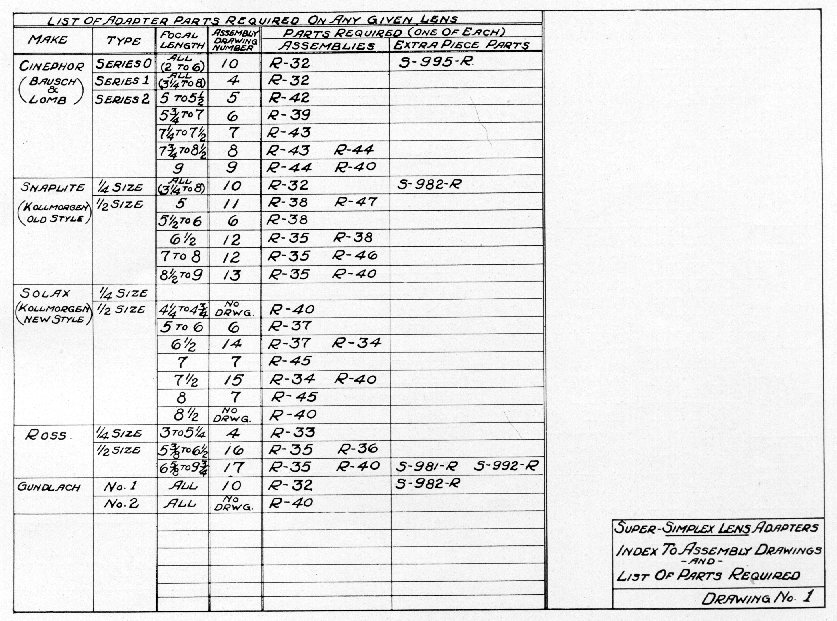
The first two drawings, Nos. 1 and 2,
list the various parts necessary to accommodate any given focal length
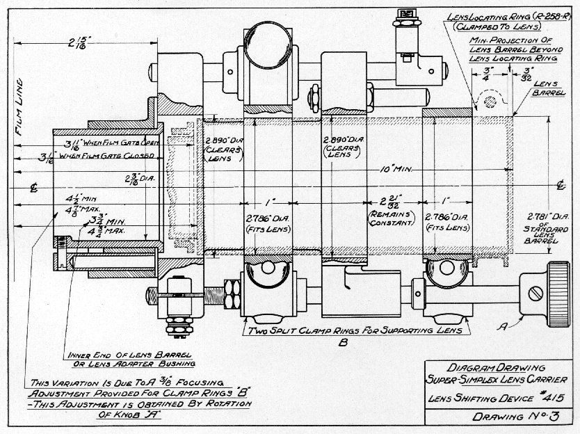
of lens of each particular make. Drawing No. 3
is an assembly drawing of the Super Simplex lens mount and lens shifting
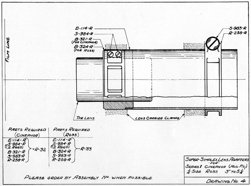
device, while drawings Nos. 4 to 17 show the lenses of various designs
with the necessary adapters assembled thereto in their proper position
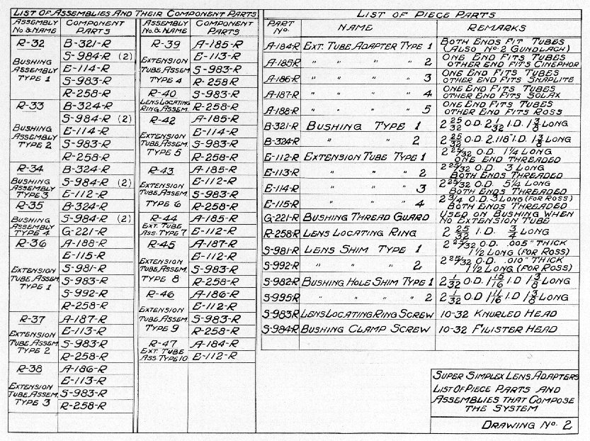
for use in the Super Simplex lens mount. By referring to drawing
No. 2 it will be noted that detailed information
is given covering drawings Nos. 1 and 3 to 17. For example, we have
a 4" Bausch & Lomb series 1 lens. By referring to drawing No.
1,
column 4, we find assembly drawing No.
4
shows the assembly necessary for this lens, and in column 5, drawing No.
1,
we find that assembly R-32 is required. Turning to drawing No. 4
we discover immediately what R32 is. We find assembly R-32 for Cinephor
requires E-114-R which is a tube having the external dimensions of a standard
series 2 or half size lens threaded on one end, two S-984-R which are the
clamp screws for B-321-R, B-321-R adapter for series 1 Cinephor lens, all
focal lengths, S-983-R clamp screw for R-258-R and R-258-R which is the
fixed focus clamp mentioned in previous instruction under FIXED FOCUS CLAMP.
(Note: R-258-R is used only where quick change lens system is desired.)
All of the above parts constitute assembly R-32. It, therefore, follows that if this assembly is ordered for the 4" series 1 Cinephor lens used in our example, and it is assembled as shown in assembly drawing No. 4, no difficulty will be experienced in using it in the Super Simplex mount.
It is apparent upon examining drawing No. 4 that approximately the same assembly is used for quarter size Ross lenses, but in order that there may be no errors, the Ross assembly is given the assembly number R-33, the only difference being the adapter for Ross lenses is B-324-R because the diameter of the quarter size Ross lens is different from that of the series 1 B. & L.
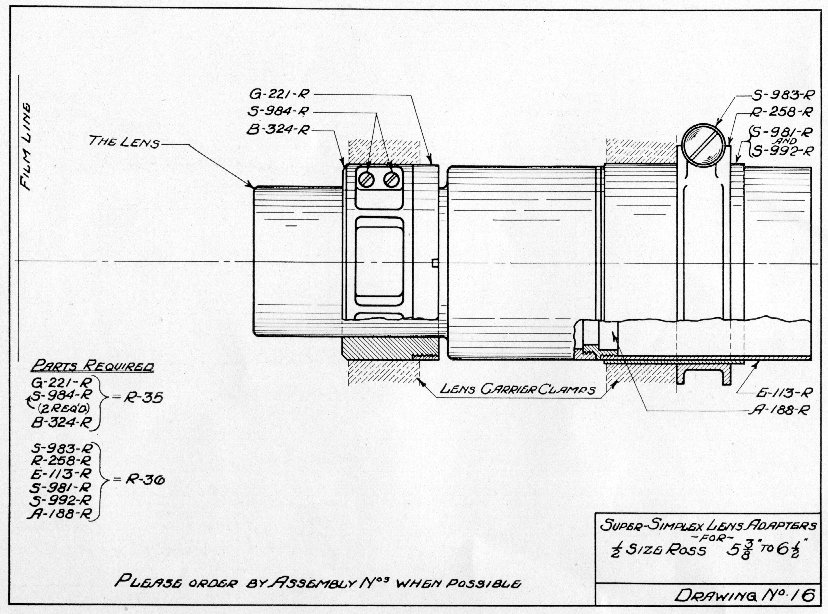
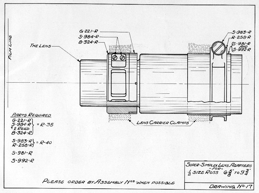
Let us take another example. You are using a 6" half size Ross lens. By referring to drawing No. 1, column 4, we find that assembly drawing No. 16 gives us the desired information and, also, in column 5 assemblies R-35 and R-36 are required. Turning to drawing No. 16 we see the assembly necessary to accommodate the Ross 6" half size lens. We find that the Ross 6" lens as supplied by the manufacturers will fit neither the front nor rear lens clamps in the Super Simplex mount. It is, therefore, necessary to use adapter assembly R-35 to accommodate the lens to the rear lens combination, and an extension tube E-113-R with threaded adapter A-188-R to lengthen the lens that it may be accommodated in the front lens clamp. It was explained in a preceding chapter on lenses that many Ross lenses are under the standard diameter and the 6" Ross lens happens to be one of these. It is, therefore, necessary to use also shim S-981-R or S-992-R, or both, to bring the extension tube E-113-R up to standard dimensions. With the parts mentioned the Ross 6" lens may be assembled as shown on drawing No. 16 and will then fit the Super Simplex lens mount. Drawing No. 16 also shows R-258 in place and, as previously explained, this is a fixed focusing collar, instructions for the use of which have been given under FIXED FOCUS CLAMP.
From these two examples it should be realized that regardless of the type of lens used, it may be readily adapted to the Super Simplex lens mount by obtaining the necessary adapter parts, all of which are shown in the succeeding drawings. All offices of the National Theatre Supply Co. are supplied with accurate information with respect to lenses for use with the Super Simplex, which can be obtained by either 'phoning or writing the National Theatre Supply Co.'s nearest office, or the International Projector Corporation, 90 Gold Street, New York City, N. Y. If the focal length and make of lens are specified when ordering Super Simplex mechanisms, the correct adapters will be shipped with the equipment from the factory. Lens manufacturers have also been furnished with all the necessary data covering lenses for use in the Super Simplex and lenses ordered in future will be supplied with the proper adapters for use in the mechanism.
The instructions in this booklet pertain solely to such changes and additions as have been made in the Super Simplex. All instructions with regard to the Simplex mechanism not given in this booklet will be found in the previous instruction book covering the regular Simplex mechanism. A careful study of this instruction book and practical application of the information given will avoid any and all difficulties which might otherwise be experienced by the projectionist. In conclusion we repeat:—any suggestions which may occur to the users of this and kindred equipment manufactured by the International Projector Corporation will be gladly received and considered.
|
|
Index To Assembly Drawings -and- List Of Parts Required |
|
|
List Of Piece Parts And Assemblies That Compose The System |
|
Super-Simplex Lens Carrier Lens Shifting Device #415 |
|
|
|
-for- Series 1 Cinephor (All F.L.) ¼ size Ross 3" to 5¼" |
|
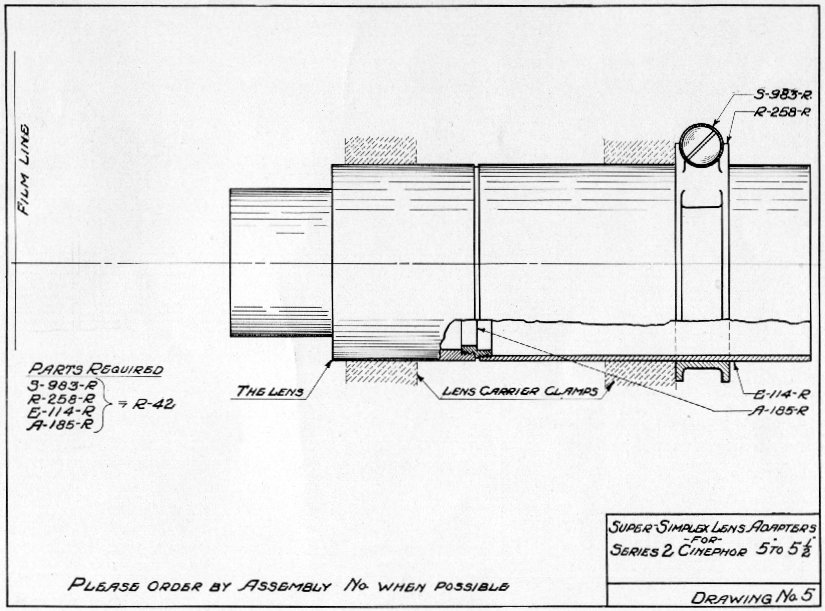
-for- Series 2 Cinephor 5" to 5½" |
|
|
|
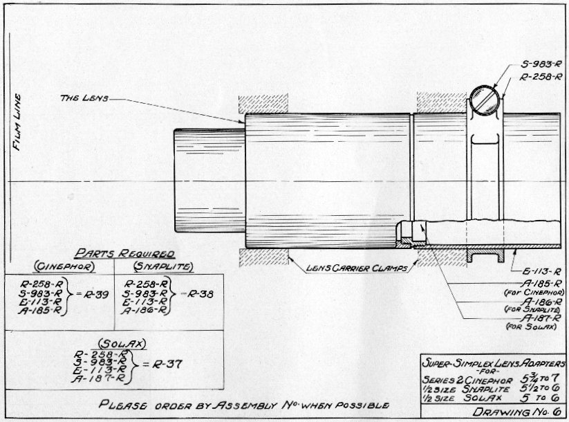
-for- Series 2 Cinephor 5¾" to 7" ½ size Snaplite 5½" to 6" ½ size Solax 5" to 6" |
|
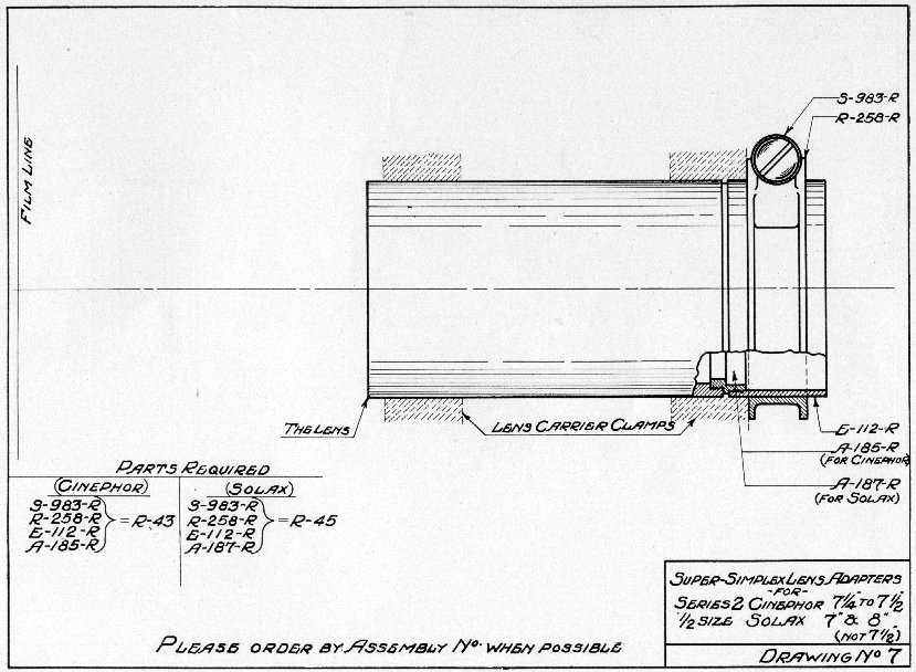
-for- Series 2 Cinephor 7¼" to 7½" ½ size Solax 7" & 8" (not 7½") |
|
|
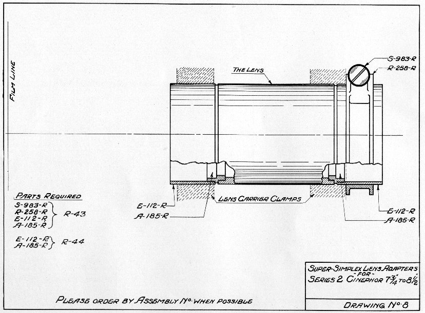
-for- Series 2 Cinephor 7¾" to 8½" |
|
|
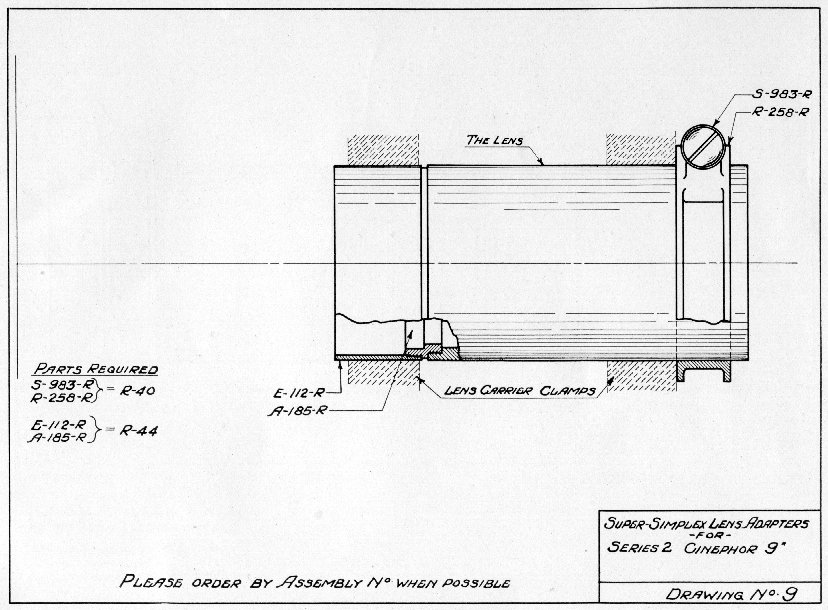
-for- Series 2 Cinephor 9" |
|
|
|
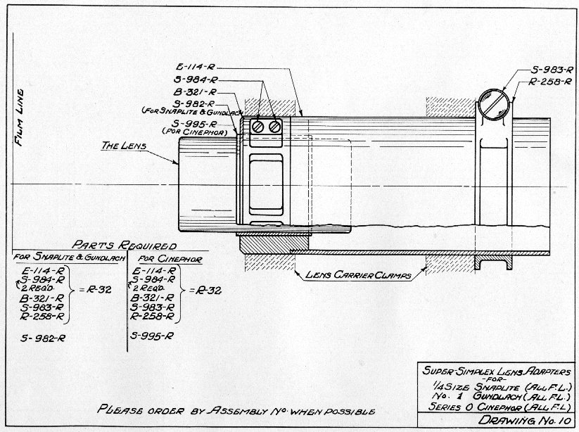
-for- ¼ size Snaplite (All F.L.) No. 1 Gundlach (All F.L.) Series 0 Cinephor (All F.L.) |
|
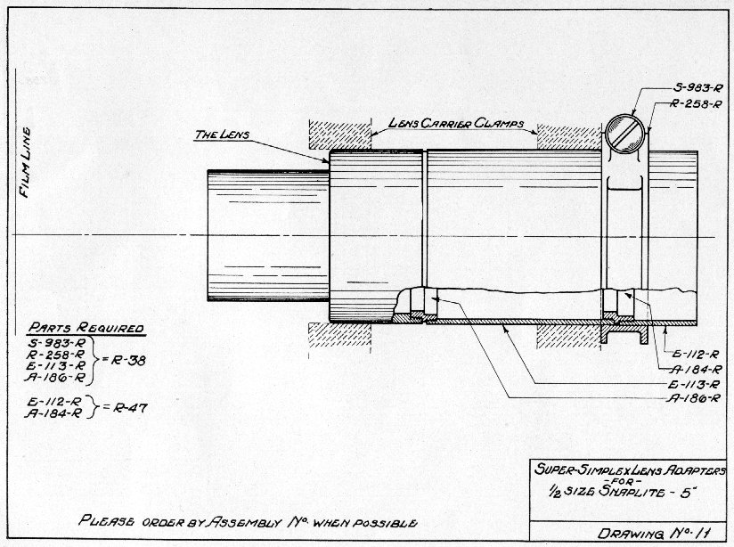
-for- ½ size Snaplite - 5" |
|
|
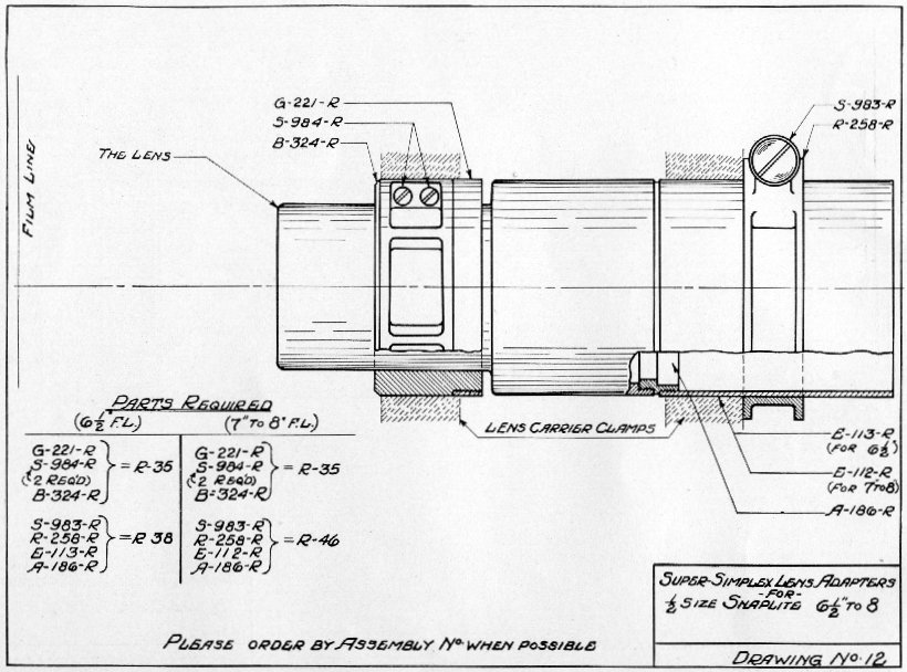
-for- ½ size Snaplite 6½" to 8" |
|
|
-for- ½ size Snaplite 8½" to 9" |
|
|
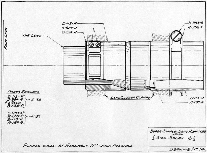
-for- ½ size Solax 6½" |
|
|
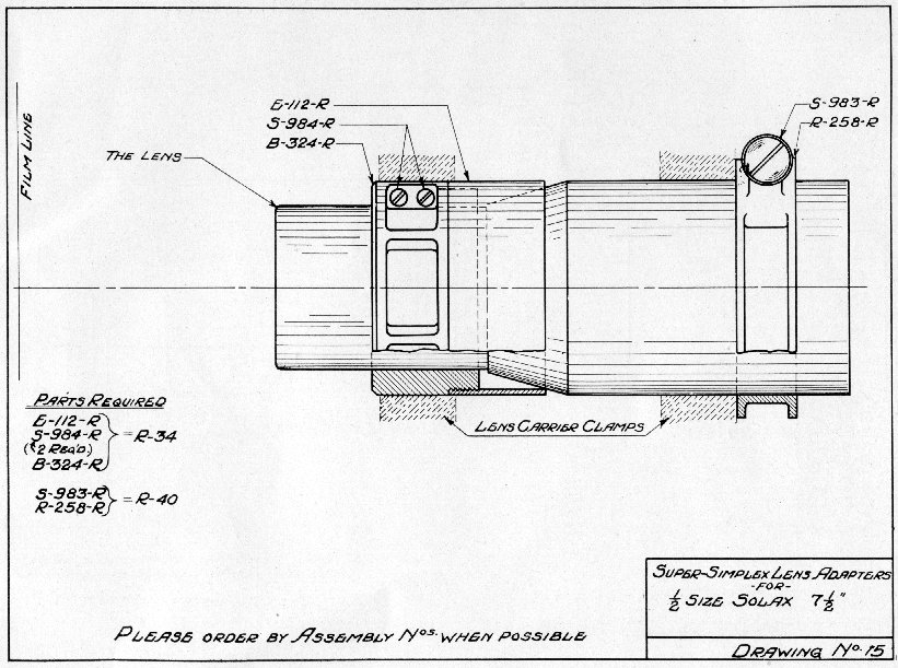
-for- ½ size Solax 7½" |
|
|
-for- ½ size Ross 5 3/8" to 6½" |
|
|
-for- ½ size Ross 6 5/8" to 9¾" |
|
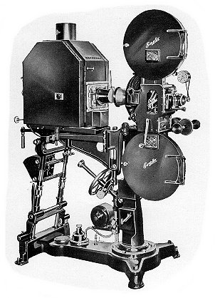
The New Super Simplex with Type M Pedestal and
H-C High Intensity Lamp.
