INSTALLATION
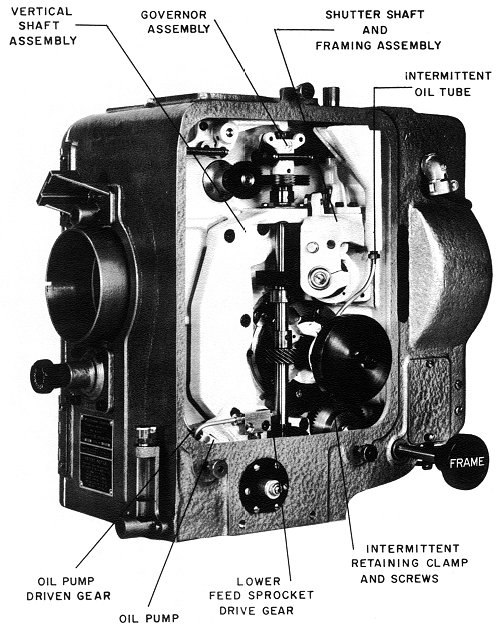
Each Simplex 35 Projector (figure
1) is carefully tested and inspected before leaving the factory.
Unless subjected to particularly severe handling during shipping, the Projector
will operate perfectly when installed. The following recommendations
should be studied carefully prior to installation. The sound system,
arc lamps, pedestals, and power conversion equipment should be installed
according to the instruction books furnished with these units.
The Simplex 35 Projector, hereinafter
referred to as the Projector, is shipped in a sturdy cardboard carton.
The required accessories are shipped with the Projector. The top
of the shipping carton is clearly marked, and there are no special instructions
needed to remove the Projector and its accessories. However, the
Projector should be thoroughly inspected after it has been removed from
the carton, and all foreign matter, which may have entered in transit,
should be removed.
The following tools and accessories are furnished with each Projector:
a. 1 G-2083 Simplex Oil Can
b. 1 P-1395 Wrench, Hex. #8 Socket Cap Screw
c. 2 G-2229 Transformers
d. 1 P-2710 Wrench, Hex. #6 Socket Cap Screw
e. 1 P-2711 Wrench, Hex. #10 Socket Cap Screw
f. 1 P-2712 Wrench, Hex. #1/4 Socket Cap Screw
g. 1 P-2713 Gem Oiler #1709 (1/2 pint)
h. 1 P-2725 Wrench, Hex. #6 Set Screw
i. 1 P-2726 Wrench, Set Screw #6 Bristol
NOTE
MOUNTING.The above tools and accessories will be needed to make adjustments and replacements. Keep them in a safe, accessible place in the projection room.
Align mechanism with soundhead using visual check on timing belt with both pulleys. Secure the two fastening bolts.
NOTE
b. When the sound mechanism includes a device to adjust the position of the Projector for proper drive, the mounting bolts should be finger tight, until the main drive and idler gear assembly has been installed. Tighten these bolts when the Projector is positioned, as stated in the following paragraphs.The main drive and idler gear assembly will drive the Projector properly without the use of shims.
MAIN DRIVE AND IDLER GEAR ASSEMBLY.
The Projector is driven from the soundhead through the main drive and idler gear assembly. A number of these assemblies are available, and the Projector can be used with a variety of soundheads.
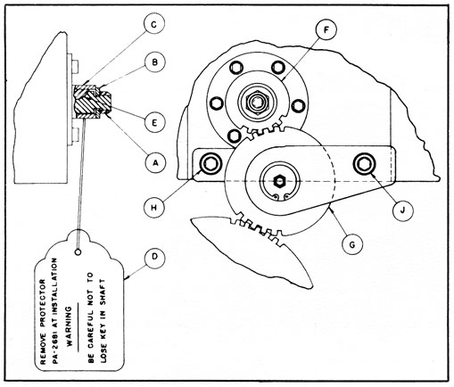
SIMPLEX FOUR STAR AND X-L SOUND AND SIMPLEX 35 MECHANISMS, WESTREX 800, SH-1000 SOUNDHEADS (G2086), RCA PA-24, PS-26, ML-1023 TO ML-1032 SOUNDHEADS (G-2130), RCA ML-1040 TO ML-1077, ML9030 TO ML-9077 SOUNDHEADS (G-2086), AND WESTERN ELECTRIC TA-7400 REPRODUCER SETS (G2129). To install the main drive and idler gear, proceed as follows. (See figure 2.)
a. Remove locknut (A) and washer (B) from the Projector and retain.
b. Remove protector (C) and tag (D) from the Projector and discard.
c. Ensure that the drive shaft key (E) remains in its slot
in the shaft.
d. Slide external main horizontal drive gear (F) on the shaft from which the protector (C) was removed, with its hub toward the Projector and its keyway in exact alignment with key (E). Secure, using washer (B) and locknut (A).Figure 2. Main Drive and Idler Gear Installation (Simplex Sound Mechanism, RCA, W. E. TA-7400, Westrex 800, and SH-1000)
e. Position idler gear bracket assembly (G) on the Projector with its gear in mesh with gear (F) and the sound mechanism main drive gear, so that its mounting holes are aligned with the mounting holes in the Projector.
f. Install fastening screws (H) and (J) finger tight. (Note the difference in length of the two screws furnished with some assemblies and install accordingly.)
g. Adjust idler gear bracket assembly (G) until there is a scarcely noticeable backlash between its idler gear, gear (F), and the sound mechanism main drive gear, at the tightest point of mesh of all gears.
h. Tighten screws (H) and (J) securely.
i. Turn Projector over by hand to check for proper mesh and readjust,
if necessary.
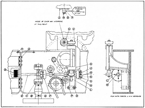
CENTURY R2 AND R6 AND WESTREX MASTER SOUNDHEADS (G-2195). To install the main drive, proceed as follows: (See figure 6.)
a. Remove three stabilizer assembly fastening screws on the operating side and withdraw assembly.
b. Loosen motor- coupling set screw (A), at the motor end.
c. Remove four vertical, shaft-bearing, housing-fastening screws (C) and remove vertical shaft with its bearings, housings, and motor coupling.
d. Remove knurled knob (D) from horizontal shaft (E).
e. Remove four horizontal, shaft-bearing, housing-fastening screws (G) and take out horizontal shaft (E) with its bearings, housings, and gears.
f. Remove collar (H), washers (J), and slide bearing and housing (K) from shaft.
g. Replace gear (L) on horizontal shaft (E) with the G-2192 drive gear and fasten with P-1367 screw (M).
h. Replace bearing and housing (K), washers (J), and collar (H). Then, fasten collar.
i. Mount Simplex 35 Projector on the sound-head and remove locknut (R) and washer (S) and retain.
j. Remove protector (T) and attach tag and discard.
k. Ensure that the key remains in its keyway in the shaft.
l. Slide P-2979 gear (U) on the shaft, from which protector (T) was removed, with its keyway in exact alignment with the key, and fasten with washer (S) and locknut (R).
m. Position G-2195 drive adapter (N), with gears (U) and (V) meshed, and finger tighten two H-1536 screws (P) and two H-1537 screws (Q).
n. Position horizontal shaft (E), modified in step (g) above, with mating gears meshed and finger tighten four fastening screws (G).
CAUTION
o. Slide knob (D) on the shaft and secure.To avoid damage to the gears, the horizontal shaft must be slid carefully into position.
p. Position vertical shaft (B) with the mating gears in mesh, the
four fastening screws (C) finger tight, and the motor coupling and motor
shaft in alignment. Then tighten set screw (A).
Figure 6. Main Drive Installation (Century R-2 & R-6 Westrex Master)
q. Raise drive adapter (N) so that its lower gear (W) is on the center line of horizontal shaft (E). Then adjust this shaft and the position of the Projector so that gears (U) and (V) and gears (L) and (W) are properly meshed, with scarcely perceptible backlash, and tighten four fastening screws (P) and (Q) and Projector fastening screws.
r. Adjust horizontal shaft (E) and vertical shaft (B) so that there is scarcely perceptible backlash between the mating gears. Then tighten four fastening screws (C).
NOTE
s. Mount stabilizer assembly and fasten.It maybe necessary to repeat steps (q) and (r) above, successively, to obtain smooth, quiet operation. It may also be necessary to adjust the motor.
t. If there is interference between the soundhead door on the nonoperating side and Projector drive gear (U), elongate holes in hinge (X) and raise door.
NOTE
u. If the soundhead door strikes one of the bearing plate fastening screws (Z), file door as required.It may be necessary to elongate the holes in the door latch and to replace shoulder screw (Y) by P-2682 shoulder screw, so that the link will not bind.
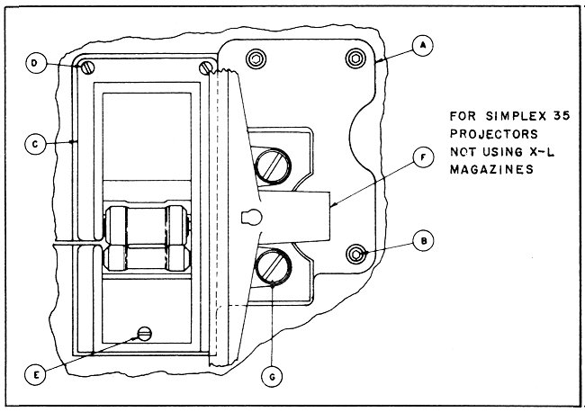
Figure 7. Simplex U-18 Magazine Installation
SIMPLEX U-18 MAGAZINE. (See figure 7.)
a. Position G-2112 roller holder assembly on (A) with its three clearance holes in alignment with the three tapped holes in (A).
b. Fasten with two H-1533 screws at one end.
c. Fasten with one H-1503 screw at the other end.
d. Position Simplex U-18 magazine on (C) with its two clearance holes in alignment with the two tapped holes in (C).
e. Fasten with two H-1531 screws,
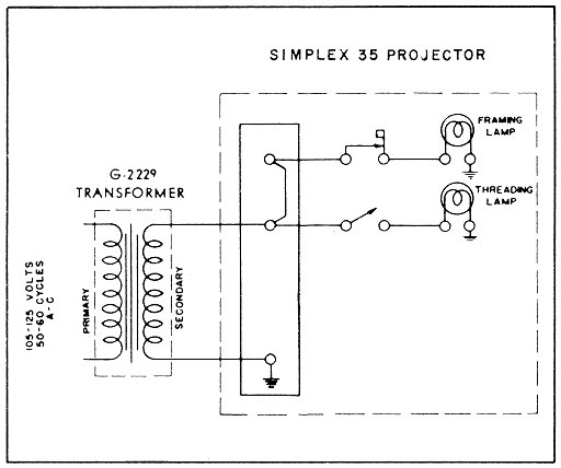
Figure 8. Light Transformer and Lamp Schematic
The G-2229 transformer furnishes
power for the framing and threading lamps in the Projector and the observation
light in the Simplex U-18 magazine. It should be mounted on the Projector
pedestal in a convenient location and the connections made as shown.
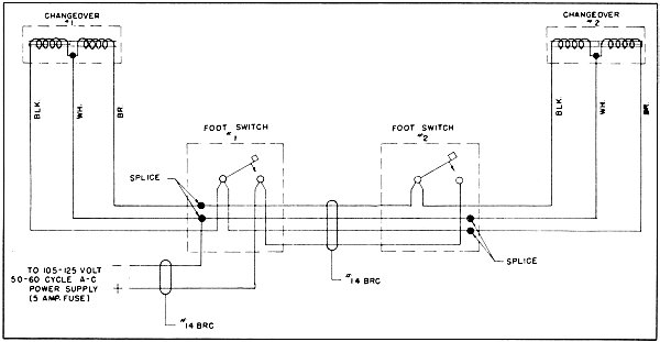
Figure 9. Picture Changeover Schematic
PICTURE CHANGEOVER. (See figure 9.)
While the Projector is equipped with an a-c picture changeover, connections should be made as shown. D-c changeovers are available.
The substitution should be made
as described in Chapter IV.
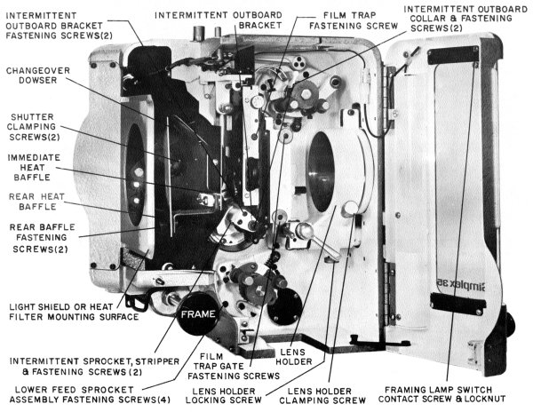
Figure 10. Film Side, Film Compartment Door Open (Sheet 1 of 2)
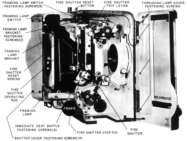
Figure 10. Film Side, Film Compartment Door Open (Sheet 2 of 2)
LIGHT SHIELD. (See figure 10.)
Mount a light shield, heat shield,
or similar device on the plate at the rear of the Projector, if required
by the particular type of arc lamp used.
Lens adapter kits, that permit the
use of all current types of lenses including the 4-inch diameter lens,
are available. The installation procedures are as follows:
ALL TYPES OF LENSES. To install all types of lenses, proceed as follows:
a. Loosen lens holder clamping and locking screws (figure 10) and rotate focus adjusting knob (figure 1) so that the lens holder is in mid-position.
b. Install lens adapter kit and projection lens (refer to the following three paragraphs) as determined by the particular projection lens to be used. When an anamorphic lens is used, refer to installation paragraph below, titled "Anamorphic Lens".
c. Start arc lamp and Projector.
d. Move lens and adapter or lens in the adapter, as required, so that the picture aperture is focused on the screen. Then, tighten lens holder clamping screw.
NOTE
e. Tighten lens holder locking screw.Open and close the film trap gate to ensure that the light shield on the rear of the lens adapter just enters the film trap gate when it is closed and does not strike the film trap gate in its extreme open position.
f. Loosen lens stop ring clamping screw and slide stop ring over lens or lens adapter.
g. Align stop ring location pin with the slot in the front of the lens holder, press stop ring against the lens holder, and tighten stop ring clamping screw.
NOTE
It is important that the lens stop ring be installed properly so that the projection lens, in its adapter, may be removed for cleaning and so that it may be reinstalled without the necessity of refocusing the picture on the screen.
FOUR
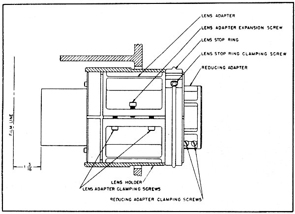
INCH DIAMETER LENSES - - ALL FOCAL LENGTHS. (See figure 11.)
To install 4-inch diameter lenses, proceed as follows:
a. Loosen lens adapter clamping screw and tighten lens adapter expansion screw sufficiently so that the lens slides readily into the adapter with its shoulder against the lens adapter.
b. Loosen expansion screw and tighten clamping screw sufficiently
to hold the lens in position.
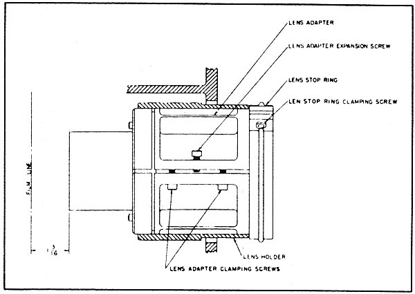
Figure
11. Lens Adapter Installation
(4-inch
Diameter Lenses)
c. Slide lens adapter into the lens holder until the rear of the light shield is 1-3/16 inches from the film line.
NOTE
d. Follow instructions in preceding paragraph to focus the picture aperture. Then complete the installation.To make this measurement, it will be convenient to remove the film trap gate per Chapter IV, paragraph titled "Film Trap Gate Assembly". When the film trap gate is reinstalled, ensure that the light shield does not interfere with its operation.
2-25/32 INCH DIAMETER LENSES -- ALL FOCAL LENGTHS. (See figure 12.) To install the 2-25/32 inch diameter lenses, proceed as follows:
Figure
12. Lens Adapter Installation
(2-25/32-inch
Diameter Lenses)
a. Loosen lens stop ring clamping screw and remove stop ring from the lens adapter.
b. Loosen two lens adapter clamping screws and tighten lens adapter expansion screw sufficiently so that the lens slides readily into the adapter.
c. Position lens temporarily midway in the adapter, loosen lens adapter expansion screw, and tighten clamping screw sufficiently to hold the lens in position.
d. Slide adapter into the lens holder until the rear of the light shield is 1-3/16 inches from the film line.
NOTE
e. Follow instructions in preceding paragraph to focus the picture aperture. Then complete the Installation.To make this measurement, it will be convenient to remove the film trap gate per Chapter IV, paragraph titled "Film Trap Gate Assembly". When the film trap gate is reinstalled, ensure that the light shield does not interfere with its operation.
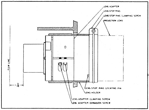
2.031, 2.118, and 2.125-INCH DIAMETER LENSES - ALL FOCAL LENGTHS. (See figure 13.) To install the 2.031, 2.118, and 2.125-inch diameter lenses, proceed as follows:
a. Loosen lens stop ring clamping screw and remove stop ring from
the lens adapter.
Figure 13. Lens Adapter Installation
(2.031", 2.118", 2.125" Diameter Lenses)
b. Loosen reducing adapter clamping screws sufficiently so that the lens slides readily into the reducing adapter.
c. Position lens midway in the reducing adapter and tighten clamping screws sufficiently to hold the lens in position.
d. Loosen two lens adapter clamping screws and tighten lens adapter expansion screw sufficiently so that the reducing adapter, with the lens, slides into the lens adapter readily.
e. Position reducing adapter midway in the lens adapter temporarily. Loosen expansion screen and tighten clamping screws sufficiently to hold the reducing adapter in position.
f. Slide lens adapter into the lens holder until the rear of the light shield is 1-3/16 inches from the film line.
NOTE
g. Follow instructions in paragraph above to focus the picture aperture. Then, complete the installation.To make this measurement, it will be convenient to remove the film trap gate per Chapter IV, paragraph titled "Film Trap Gate Assembly". When the film trap gate is reinstalled, ensure that the light shield does not interfere with its operation.
ANAMORPHIC LENS. To install the anamorphic lens, proceed as follows:
a. When other than a 4-inch diameter projection lens is used, the anamorphic lens should be attached to the projection lens, using the adapter furnished by the lens manufacturer. Install the combination in the lens holder, as described in the preceding paragraphs.
b. When a 4-inch diameter projection lens is used, a support is required
for the anamorphic lens. It is supplied as the G-2335 lens mounting
kit and should be installed in accordance with the instructions supplied
with the kit.
REMOVING AND INSTALLING THE PROJECTION LENS. To remove the projection lens, proceed as follows:
a. Loosen lens holder clamping screw (figure 10) and withdraw projection lens and adapter as a unit.
NOTE
b. To reinstall the projection lens and adapter when its position has not been changed in the adapter, slide adapter into the lens holder, align lens stop ring pin with the slot in the lens holder, press lens stop ring against lens holder, and tighten lens holder clamping screw. It should not be necessary to refocus the picture on the screen, if the removal and replacement are carefully carried out.The lenses may be cleaned without removing the projection lens from its adapter, or changing its position in the adapter.
NOTE
If the projection lens is to be replaced, the procedure for the lens adapter used should be followed.
Aperture plates, for the several screen ratios,
may be ordered. Undersize plates are used with either flat or curved
screens.
a. Remove film trap gate (refer to figure 14 and Chapter IV, paragraph titled "Film Trap Gate Assembly Removal"). Inspect the film runners for dirt, grit, or other foreign material, and clean with a cloth.
b. Remove film trap (refer to figure 14 and Chapter IV, paragraph titled "Film Trap Assembly Removal"). Inspect pressure straps and lateral guide rollers for dirt, grit, or other foreign material, and clean with a cloth.
c. Inspect entire film compartment carefully for operation of pad rollers and film trap gate. Be sure all parts are clean.
d. Rotate Projector over by hand and observe operation on both film
and gear sides. It should turn freely and smoothly.
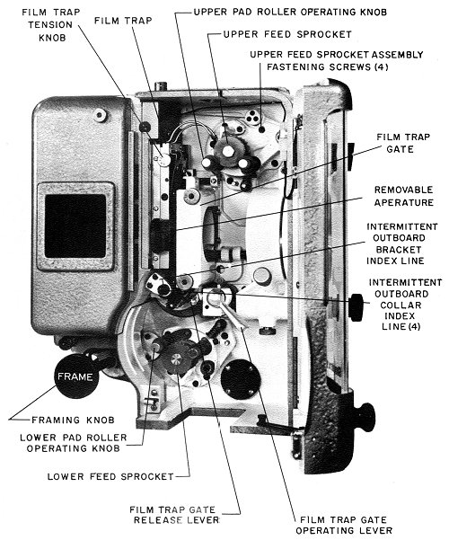
Figure 14. Film Side
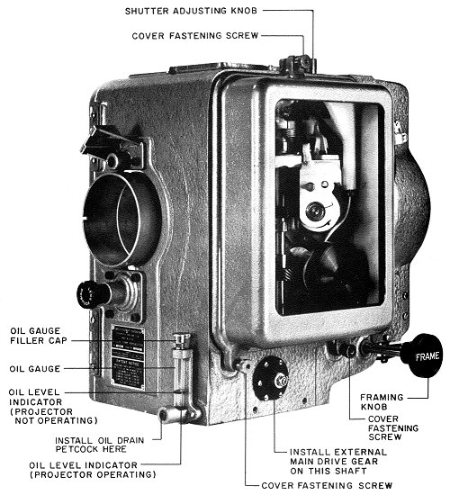
Figure 15. Gear Side, Cover Closed
INITIAL LUBRICATION. (See figures 15, 16, and 17. )
NOTE
a. Set black oil level indicator ring on the oil sight guage as shown in figure 16 or 17. The drain plug in the oil gauge must be tight.When the Simplex 35 Projector is used in drive-in theatres, the oil gauge is mounted at the rear of the Projector and the oil f ilter is located in the rear of the gear compartment, instead of as shown in figures 18 and 19.
NOTE
When the projection angle is not exactly as shown in the chart, select the nearest angle, and raise or lower this ring to conform to the actual projection angle.
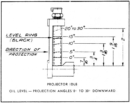
Figure 16. Oil Level (Projection Angles 0ş to 30ş Downward)
b. Raise sleeve around the shutter adjusting knob and, using it as a funnel, pour Simplex Projector oil into the mechanism until the oil level is at the black indicator ring.
CAUTION
If this oil level is exceeded, there may be leakage around the main, horizontal drive gear shaft and bearing on the gear side of the Projector. Only genuine Simplex Projector oil should be used. Any other oil may cause serious operating difficulties and will void the factory guarantee.
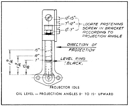
Figure 17. Oil Level (Projection Angles 0° to 15° Upward)
c. Start Projector and run for at least one minute. Check for an oil splash on the gear compartment cover glass.
d. Rotate Projector over by hand and observe operation on both film and gear sides. It should turn freely and smoothly.
CAUTION
Only when absolutely necessary, remove gear compartment cover and only after releasing all three cover fastening screws. Before replacing the cover, wipe all oil from the cover gasket and the mating surface on the Projector. Any oil remaining on these surfaces will provide an oil creepage path after the cover is fastened. Tighten all three cover fastening screws (figure 15) equally and finger tight, just enough to form an oil-tight seal.
Figure 18. Gear Side, Gear Compartment Cover Removed (Front View)
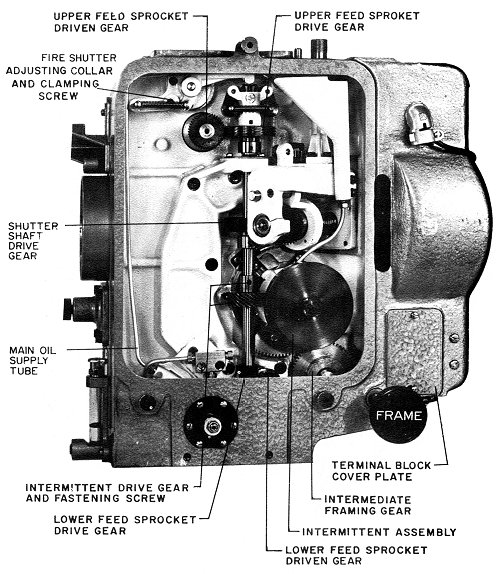
Figure 19. Gear Side, Gear Compartment Cover Removed (3/4 View)
a. Start Projector and observe operating performance, particularly with respect to lubrication and the main drive and idler gear assembly.
b. There should be an oil splash on the gear compartment cover and a steady, light flow of oil, (just more than a drip) from the oil tube just above the intermittent gear. (See figure 19. )
c. If gear whine is apparent, adjust main drive and idler gear assembly for minimum gear whine, while the Projector is running.
NOTE
While some gear whine may be noticed initially, it should disappear after a few hours of operation. Since the Projectors have been "run-in" carefully at the factory, no "run-in" period is required after installation.
d. Thread a suitable film in the Projector, as follows: (See
figure 14. )
1. With the film compartment door open, rotate Projector by hand until one of the four index lines on the intermittent shaft collar coincides with the red index line on the intermittent outboard bearing bracket. The intermittent sprocket will then be at rest and in proper position for threading.
2. Set framing knob (figure 1) in central position.
3. Open upper and lower feed sprocket pad rollers.
4. Open film trap gate by rotating film trap gate operating lever toward the rear of the Projector.
5. Thread, with the film in frame, at the framing aperture above the film trap (figure 10) and with upper and lower loops as shown.
NOTE
6. As threading progresses, close the upper feed sprocket pad rollers, the film trap gate (by pressing the film trap gate release lever in the direction of gate closure and downward about 45 degrees), and the lower feed sprocket pad rollers.The framing lamp (figure 10) lights automatically when the film compartment door is open, thus simplifying proper framing.
7. Check for proper threading and close film compartment door.
e. Strike arc, start the Projector, observe the picture on the screen,
and adjust focus.
SHUTTER ADJUSTMENT. (See figure 19.)
a. The shutter is set at the factory at 84°, when used in conjunction with a standard movement. Since the Projector is shipped with a standard movement, no adjustment should be necessary. The picture should be checked for "travel ghost", and, if necessary, the shutter adjusting knob (figure 15) should be turned to eliminate the ghosting. When a high-speed intermittent movement is used for indoor or drive-in operations, the shutter should be set initially at about 60°, and the picture checked for travel ghost as follows:
1. Loosen four screws which secure the shutter blades and make a rough setting at or near 60°.
2. Run Projector with film and check for ghost. If ghost appears, the shutter blades should be opened until the ghost disappears.
3. If no ghost appears, close blades until the first trace of ghost appears, then open them until it disappears. This is the correct shutter opening,
4. Tighten four screws.
NOTE
The shutter range is from 47° through 92° and it may be adjusted through that range, depending on light requirements.
FILM TRAP TENSION.
(See figure 14.)
a. Set film trap tension knob for minimum tension (extreme counterclockwise position).
b. The film trap tension was accurately adjusted at the factory. If absolutely necessary, and to obtain a steady picture, the film trap tension knob may be turned clockwise, one position at a time, while the film is running.
CAUTION
Always adjust for the minimum tension that gives a steady picture. Excessive tension not only increases wear on parts, but in extreme cases may cause torn sprocket holes and film breakage.